Quick Start Guide
This module works by periodically collecting the network topology graph data of the supported networking software or formats. The data has to be either fetched by the application or received in POST API requests, therefore after deploying the application, additional steps are required to make the data collection and visualization work, read on to find out how.
Creating a Topology

Create a topology object by going to Network Topology > Topologies > Add topology.
Give an appropriate label to the topology.
Select the topology format from the dropdown menu. The topology format determines which parser should be used to process topology data.
Select the Strategy for updating this topology.
If you are using FETCH strategy, then enter the URL for fetching topology data in the Url field.
If you are using RECEIVE strategy, you will get the URL for sending topology data. The RECEIVE strategy provides an additional field expiration time. This can be used to add delay in marking missing links as down.
Sending Data for Topology with RECEIVE Strategy

Copy the URL generated by OpenWISP for sending the topology data.
E.g., in our case the URL is
http://127.0.0.1:8000/api/v1/network-topology/topology/d17e539a-1793-4be2-80a4-c305eca64fd8/receive/?key=cMGsvio8q0L0BGLd5twiFHQOqIEKI423.Note
The topology receive URL is shown only after the topology object is created.
Create a script (e.g.:
/opt/send-topology.sh) which sends the topology data usingPOST, in the example script below we are sending the status log data of OpenVPN but the same code can be applied to other formats by replacingcat /var/log/openvpn/tun0.statswith the actual command which returns the network topology output:
#!/bin/bash
# replace COMMAND with the command used to fetch the topology data
COMMAND="cat /var/log/openvpn/tun0.stats"
UUID="<TOPOLOGY-UUID-HERE>"
KEY="<TOPOLOGY-KEY-HERE>"
OPENWISP_URL="https://<OPENWISP_DOMAIN_HERE>"
$COMMAND |
    # Upload the topology data to OpenWISP
    curl -X POST \
        --data-binary @- \
        --header "Content-Type: text/plain" \
        $OPENWISP_URL/api/v1/network-topology/topology/$UUID/receive/?key=$KEY
Add the
/opt/send-topology.shscript created in the previous step to the crontab, here's an example which sends the topology data every 5 minutes:
# flag script as executable
chmod +x /opt/send-topology.sh
# open crontab
crontab -e

## Add the following line and save

echo */5 * * * * /opt/send-topology.sh
Once the steps above are completed, you should see nodes and links being created automatically, you can see the network topology graph from the admin page of the topology change page (you have to click on the View topology graph button in the upper right part of the page) or, alternatively, a non-admin visualizer page is also available at the URL
/topology/topology/<TOPOLOGY-UUID>/.
Sending Data for ZeroTier Topology with RECEIVE Strategy
Follow the procedure described below to setup ZeroTier topology with RECEIVE strategy.
Note
In this example, the Shared systemwide (no organization) option is used for the ZeroTier topology organization. You are free to opt for any organization, as long as both the topology and the device share the same organization, assuming the OpenWISP controller integration feature is enabled.
1. Create Topology for ZeroTier
Visit
admin/topology/topology/addto add a new topology.We will set the Label of this topology to
ZeroTierand select the topology Format from the dropdown asZeroTier.Select the strategy as
RECEIVEfrom the dropdown.
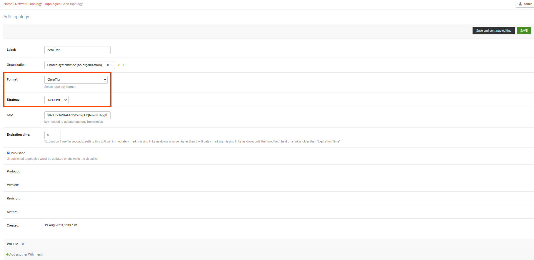
Let use default Expiration time
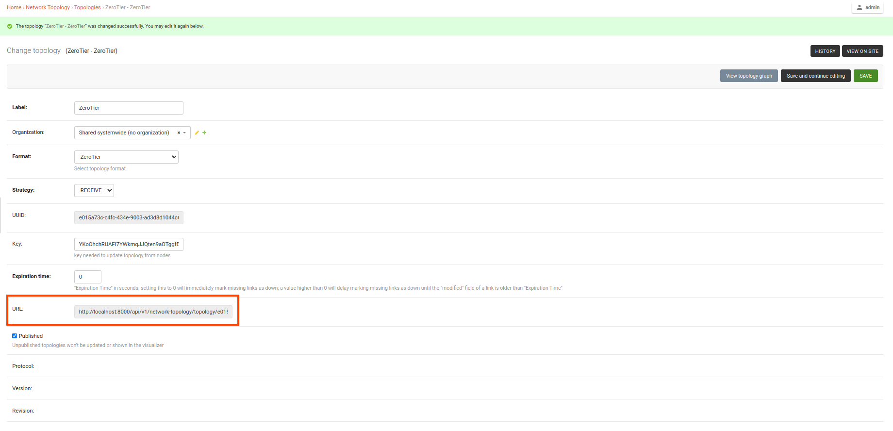
0and make sure Published option is checked.After clicking on the Save and continue editing button, a topology receive URL is generated. Make sure you copy that URL for later use in the topology script.
2. Create a Script for Sending ZeroTier Topology Data
Now, create a script (e.g:
/opt/send-zt-topology.sh) that sends the ZeroTier topology data using a POST request. In the example script below, we are sending the ZeroTier self-hosted controller peers data:
#!/bin/bash
# command to fetch zerotier controller peers data in json format
COMMAND="zerotier-cli peers -j"
UUID="<TOPOLOGY-UUID-HERE>"
KEY="<TOPOLOGY-KEY-HERE>"
OPENWISP_URL="https://<OPENWISP_DOMAIN_HERE>"
$COMMAND |
    # Upload the topology data to OpenWISP
    curl -X POST \
        --data-binary @- \
        --header "Content-Type: text/plain" \
        $OPENWISP_URL/api/v1/network-topology/topology/$UUID/receive/?key=$KEY
Add the
/opt/send-zt-topology.shscript created in the previous step to the root crontab, here's an example which sends the topology data every 5 minutes:
# flag script as executable
chmod +x /opt/send-zt-topology.sh
# open rootcrontab
sudo crontab -e

## Add the following line and save

echo */5 * * * * /opt/send-zt-topology.sh
Note
When using the ZeroTier topology, ensure that you use sudo
crontab -e to edit the root crontab. This step is essential
because the zerotier-cli peers -j command requires root
privileges for kernel interaction, without which the command will
not function correctly.
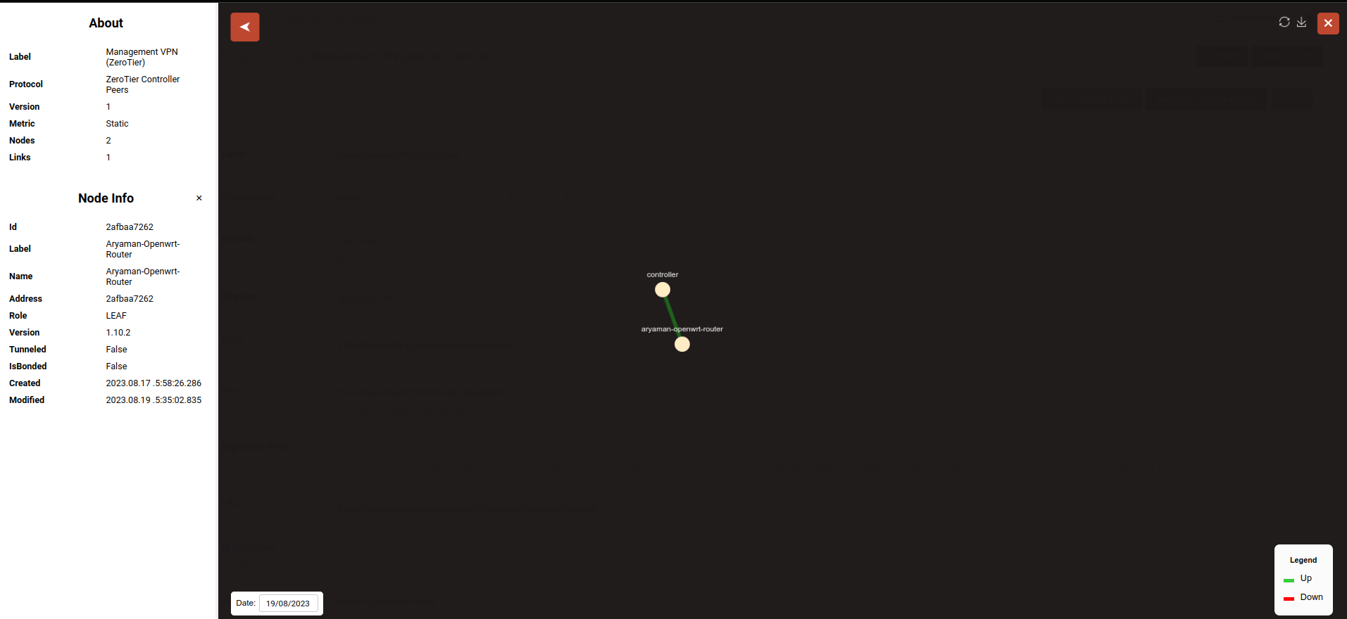
Once the steps above are completed, you should see nodes and links being created automatically, you can see the network topology graph from the admin page of the topology change page (you have to click on the View topology graph button in the upper right part of the page) or, alternatively, a non-admin visualizer page is also available at the URL
/topology/topology/<TOPOLOGY-UUID>/.